Layout Designer Marking and Traceability Software
-
Accueil Pryor
›
-
Produits
›
- Layout Designer Marking and Traceability Software


Layout Designer Marking and Traceability Software
Layout Designer (also known as Project Designer in some versions) is a marking and traceability software module where marking projects are created and controlled, with the ability to link to an external database and control user access. This software module contains a range of standard and optional features including duplication checking and data reporting
- Create marking projects
- Control a marking machine
- Log mark data with duplicate checks
- Wide range of data access features allows easy integration
- Create and search reports on a local database
- Access/control User Manager functions
Si vous souhaitez obtenir de plus amples informations sur ce produit, veuillez remplir le formulaire de demande et un membre de notre équipe prendra contact avec vous.
Présentation
Marking and Traceability Software
Layout Designer is a software module in Pryor’s marking and traceability software suite. Installed on a PC, the main functions of this module are to create marking projects, access and record marking data and control a marking machine, including dot peen, laser, scribe and chemical etching machines.
MarkMaster User Guide Videos:
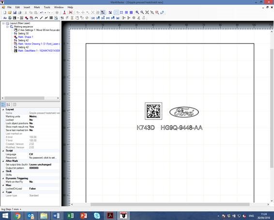
Inserting text and a Data Matrix code into a marking layout
Inserting an auto height sensing function into a marking layout
Using a Pryor controller to track the moves of a marking head
Marking a logo with a Pryor laser
Create Marking Projects
Marking projects are designed and tested in Layout Designer. Projects can be created using the machine controller PC or created remotely and stored centrally, for a machine operator to access.
Layout Designer enables the user to create a marking project, such as insert variables, manage unique marks, verify marks and create reports. Users can also set up and control additional marking and verification apps and equipment. A completed marking project contains all the instructions for the PC and marking equipment to perform during the marking sequence.
The drag and drop editor for the elements to be marked. All the following can be inserted and edited at the click of a mouse:
-Data Matrix codes
-TrueType fonts
-Logos and images
-Serial numbers
-automatically incrementing with each mark made
-automatically generated within a given format
-input from a database or production system
-Dates and date codes in the format of your choice
-Variable text/data from a barcode reader, dialogue box or other input
-1D barcodes (laser and chemical etching products only)
Users can insert and import a range of graphic objects within the marking sequence, including vector drawings, such as a CE mark. Formats supported are HPGL 1&2 (plt) and dxf CAD files. For laser marking machines, users can also import bitmap graphical objects in jpg, jpeg, and png file format.
The most commonly used functions are serial numbering, using automatic incrementation or data from a separate file/IT system, and graphic layouts for marking logos alongside batch numbering. Users can insert a range of standard objects such as an arc, which numbers or text can be marked along, or use the polyline function, which allows the user to create objects.
Marking objects can updated at a local and global level, ensuring layouts can be edited in one place within the software, and all layouts that are linked to it are automatically updated with that value the next time they are loaded.
The Operator Instructions feature within Layout Designer allows work instructions and prompts to be inserted within the marking sequence which are then presented to the machine operator. Operator instructions can consist of titles, instructions and images or other media such as web pages or video. These instructions will appear in the Production Interface module of Pryor’s marking and traceability software suite.
Accessing External Files
Pryor’s marking and traceability software offers the widest range of data access features, for easy integration with existing systems. Each marking project can be linked to an external file, such as an Access, Excel or CSV file. This feature allows manufacturers to access data, such as serial numbers, from their own IT system e.g. CRM, ERP, MES and PLM.
User Manager
Database security is ensured with protected use; fully configurable user rights to prevent the creation of fraudulent records. The User Manager feature in Layout Designer provides administration functions to limit the access of different users. The administrator can set defaults and passwords for users and establish user groups. When additional apps and equipment are in use, the administrator can change the application settings and access an audit log.
Data Recording
Layout Designer can access and record mark data onto an external database, whilst performing duplicate checks on the local PC. The marking process is linked to automatic record creation, allowing the software to log all data marked by the machine to the database. Records can only be created when an item is marked, eliminating the possibility of an error in the database.
Layout Designer will also perform duplicate checks to make sure data has not been marked before. This feature allows the software to search the database at the beginning of a marking cycle to see if the value has already been marked. If a duplicate is found, an error message is displayed showing when it was last marked. This is a powerful feature designed to prevent duplicate serial numbers being marked on different components.
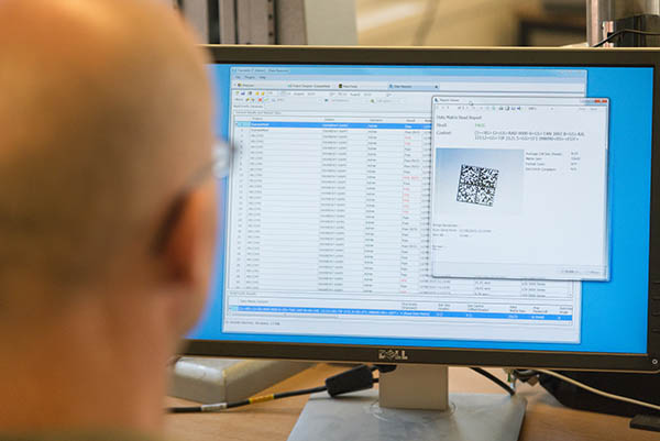
Data Reporter
Users can visualise, search and create reports from the local database. The flexibility of configurable data collection, combined with the volume of data which can be logged during marking, can add significant value to a database.
Bespoke Development
Get in touch with the Pryor team to find out more about our bespoke machine, automation and software design services.
Technical Help
Pryor has a range of technical support articles:
Industry 4.0 and the Importance of Product Traceability
Use Traceability to Error-Proof your Manufacturing
Can't find what you're looking for? Contact the Pryor team
Présentation
Overview Video for MarkMaster Marking and Traceability Software
Présentation
Technical Information for Layout Designer Marking and Traceability Software
|
User Interface Features |
|
|
Marking Sequence Panel |
Projects are displayed and processed in order of the marking sequence |
|
Project Properties Panel |
Range of features to configure the position and behaviour of the mark |
|
Project Object Properties Panel |
Configure objects within the project marking sequence |
|
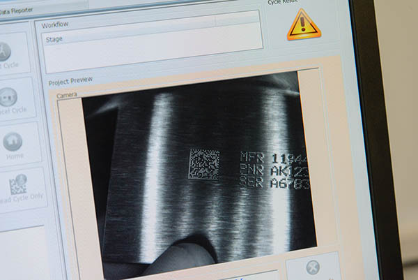
Project Preview Panel |
Displays a preview of the mark and allows objects to be selected, dragged, resized etc. |
|
Mark Dialogue Event Log |
As the mark progresses the operator is informed of the current cycle state |
|
Training Mode |
Create test marks and templates |
|
|
|
|
Commonly Used Features |
|
|
Autosave Layout After Each Mark |
Useful when marking serial numbers to ensure the last marked number is saved to the layout to prevent the risk of duplication |
|
Autosense |
Enables a dot peen machine to sense the height of the work piece and mark, ideal for marking different work piece heights with the same depth of force every time |
|
Auto-Start Scripts |
If any scripts have been assigned to the layout then run them as and when required. Do not wait for any manual intervention from a user |
|
Batch Serial Number |
Inserts a Batch Serial Number into the current layout. A more sophisticated serial number that can prompt for batch sizes to be entered for batch counting during marking |
|
Circumferential Part |
This setting is used to configure the marking machine to mark around the circumference of a part using an additional part rotating axis called a circumferential axis |
|
Data Matrix |
Data Matrix configuration. Cell size increase as more data is added or overall size can be controlled |
|
Data Matrix Templates |
Creates template data formats, useful for defining Application Identifiers (AIs), Data Identifiers (DIs) or Text Element Identifiers (TEIs) within ISO 15434 |
|
Database Test Station |
Allows a user to set up the connection string and test the connection to a pre-selected database, Excel or CSV file |
|
Digit Sequences |
The digit sequence properties teach the software how to count serial numbers. This allows custom counting methods to be defined |
|
Enable Serial Out for Text-Based Layout Elements |
When marking text-based elements the text can also be sent out via a serial port to a printer or other device |
|
Feature Finder |
Works in conjunction with a machine vision camera to find a feature which can be used as a marking start point |
|
Feature Offset |
Designed to guide either a robot or a marking head in an XY plane based on the output from a machine vision camera. Commonly used to detect a part feature which is used to offset the marking head/robot to an offset position relative to the feature, effectively tracking the location of the part and allowing the marking system to mark a part that is not always presented in the same location |
|
Follow Mark Path |
Track moves will follow the mark path to an object if on, if not will take the most direct route. Used to steer around obstacles if the part is not flat |
|
Global Serial Number |
Inserts a Global Serial Number into the current layout. A global serial number will increment globally across all layouts that use it |
|
I/O Control |
Used for controlling digital inputs and outputs |
|
Increment By |
Specifies by how much the serial number should increment by |
|
Increment Every |
Specifies how often the serial number should increment. This is useful if three parts need to be marked with the same serial number. Setting the Increment Every property to 3 will then mark 3 parts before incrementing the serial number |
|
Label Feed Settings |
Used to configure the behaviour of automatically feeding labels or tags under the marking head (includes multiple feeds, collection hoppers, electrically/pneumatically driven) |
|
Language |
Indicates which scripting language is in force |
|
Layout Template |
Graphical representation of the part being marked to be shown in the background of the marking preview. If the part being marked is correctly scaled on screen it can provide a useful method of aligning the marking objects on the part |
|
Load Most Recent Script |
Loads the last layout used at start-up |
|
Load Most Recently Used Layout |
Loads the last layout used at start-up |
|
Lock Objects |
Once the project has been saved for the first time, it can be locked to avoid accidental changes |
|
Marking Units |
Metric (mm) or Imperial (inch) can be set on a per project basis |
|
Operator Instruction |
Allows work instructions to be presented to the machine operator at any stage within the marking sequence (presented in Production Interface module) |
|
Password Control |
Control access levels for each user |
|
Planar Part |
Used to operate in both planar and circumferential modes. E.g. to mark a cylindrical part around the outer circumference and a flat machined section on the same part |
|
Refresh Layout Elements in Real-Time |
Enable feature to refresh data on the layout in real time. The layout element is marked using data accurate at the time the mark is made |
|
Remote IO Settings |
Allows an external device to control and monitor the marking system using the marking controllers digital I/O port |
|
Replicator Part |
Marks the same marking object such as text and Data Matrix codes multiple times e.g. to mark trays of identical components and other similar applications |
|
Reset Every |
The Reset property allows serial numbers to be reset on certain events e.g. it is possible to reset the serial number to 00001 (if digits are set to 5) when the Day changes, Week Changes, Month Changes, Year Changes or Shift Code changes |
|
Script Import |
Supports a powerful scripting engine. Scripts based on the following programming languages can be developed and executed at any stage of the marking sequence:
|
|
Serial Number |
Inserts a layout Serial Number into the current layout. The layout serial number will only affect the layout it is used in |
|
Shift Codes |
Inserts default shift patterns and what gets marked for those shift patterns |
|
Shifts |
Allows creation of working shifts which may be incorporated in the mark to identify which shift marked the component |
|
Use Top Left as Layout (0,0) as Origin |
To use the top left of the marking area as the (0,0) origin |
|
Version Control |
Created/Modified version indicator |
|
Wait for Start Button |
The marking cycle will not commence until the start button on the marking machine or local start/stop station is pressed. Useful if a part needs to be manually repositioned mid-way through the marking cycle |
|
Warn if Layout Element Out of Bounds |
Warns user if any layout items are outside the marking area |
|
X, Y, Circ Offsets |
Offset marking of objects e.g. X = 20 moves everything to the right by 20mm |
|
X, Y, Z, Circ Park |
Normally the marking head will go home to its 0,0,0 position. This allows the head to be 'parked' closer to the part to be marked, and can speed up throughput of parts |